Application workflow
We need to picture the application workflow as a Data Pipeline that helps you process and move data between different processing steps.
The processing steps are the nodes of a Directed Acyclic Graph (DAG).
A directed graph may be used to represent a network of processing elements; in this formulation, data enters a processing element through its incoming nodes and leaves the element through its outgoing nodes.
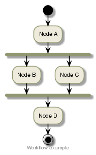
Below an example of a Directed Acyclic Graph depicting a classical workflow where:
- Node A will process the data coming from the workflow sources
- Node B and Node C will process the data generated by Node A
- Node D will process the data generated by Node B and Node C
|
|
Tip
- Take the time to carefully think how to structure the workflow by answering the questions:
- How many nodes do I need?
- Can the node execution be split in several tasks?
- What will each node read as inputs?
- What will each node write as outputs?
- What parameters does each node need?
- Is my workflow cost-effective in terms of I/O?
- Below a few examples of workflows:
-